Hello i'm simulating my circuit with a transient simulation and i wanted to calculate the current drawn for different temperatures. here i have some questions: is this current the total current or only the dynamic one? note that there's nothing changing in the circuit but a clock fed to some digital inputs. I tried using some functions in the calculator to get this current as a function of temperature like average but the problem is that the value changes with the transient time, also for the integ function, so i wanted to know which function should be suitable to estimate the current over the whole time not only the transient one.
↧
Calculating the current from a transient simulation
↧
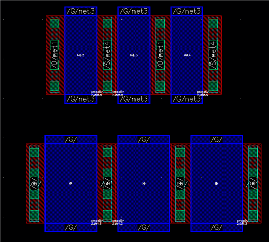
Can't see layers of the components
I have a problem When I try to zoom in order to see the layers of the device .
I tried to increase stop in options -> display but it shows me a " X " fill. I tried to change properties, but I don't know exactly the properties to add, chould I modify cell properties or instance properties.
Your help appreciated
↧
↧
Ring oscillator simulation results are not reliable (Jitter/Frequency)
Hi,
I am currently designing an ring oscillator of 100-200 MHz frequency, and have to measure the absolute jitter using transient simulation.
The schematic consists of a 5 stage ring oscillator and an ideal voltage source of 1 V to power the osc.
A jitter was measured using abs_jitter function, which is a built-in function in the calculator of ADE X environment.
Since the function compares and measures a switching timing difference between the osc and an ideal clock, if any noise source is not included in the circuit, resulting jitter value should be same, if simulated well.
However, whenever I simulate the circuit, changing some settings like simulation time or an additional circuit, jitter varies dramatically even though the schematic is not changed.For example,
(Simulation 1-1) The peak to peak of the jitter (jpp) was calculated as 0.042 zs (zs: 10^-21 second)
(Simulation 1-2) However, jpp becames 400 zs when I changed simulation time to 50 us from 10 us.
(Simulation 1-3) Also, when I changed simulation time to 500 us, jpp varies to 26 as (as: 10^-18 second)
(Simulation 2) When I inserted dummy transistors in the schematic, jpp was measured 43 zs (Simulation time: 10 us)
(Simulation 3-1) When I inserted a dummy sine wave in the schematic, jpp becames to 120 zs (Amplitude: 100mV, Freq: 900 MHz). In this case, the osc frequency was increased by 60 kHz.
(Simulation 3-2) When I changed the the dummy signal frequency to 9 GHz, jpp becames to 1 fs. Also, the osc frequency was increased by 80 kHz.
Since the theoretical jitter of ideal osc is 0 s, and also since it might be difficult to output '0' by subtracting two values, the result of as to zs order might be reasonable value.
However, I think the inconsistency of jpp should be checked.Also, the frequency shifting by a dummy signal is a serious issue. It must be solved.
Why it happend and how to address the problem ?
Thank you in advance !
↧
Vary transistor parameters using Monte Carlo simulation (the statistical blocks: Process and mismatch).
Hello colleagues,
I am using Virtuoso version IC6.1.18 and Spectre -subversion 18.1.0.077.
I have tried both the Classic Spectre Simulation and the ADE XL tool to run Monte Carlo simulations (MCs) on a ring oscillator circuit. The Model Card used for this design is model n bsim3v3 and model p bsim3v3 (myModel.scs). Simulation configurations were configured on a cfg control file by using the following command in the standalone (Classic Spectre Simulation):
spectre +config cfgMonteCarlo1 inverter_ring.scs
The cfgMonteCarlo1 and the inverter_ring.scs attached to this post.
The simulations were simulated successfully and their results were plotted in the viva XL tool for both tools (Classic Spectre Simulation and the ADE XL).
I read the following documents:
- Spectre® Circuit Simulator Reference, Product Version 18.1,
- Spectre® Classic Simulator,
- Spectre Accelerated Parallel Simulator (APS), and Spectre Extensive Partitioning Simulator (XPS) User Guide, Product Version 18.
Also, I joined the online course Virtuoso Analog Simulation: T3 Monte Carlo Simulations Using ADEXL.
They explained about the commands how to vary transistor parameters in Spectre® Circuit Simulator Reference document and in the T3 online course but when I used these commands to vary transistor parameters by using the statistical blocks (Process and mismatch) as in cfgMonteCarlo2 file showed these errors:
Error found by spectre during hierarchy flattening.
ERROR (SFE-11): Unknown parameter `l' specified in process vary statement.
ERROR (SFE-11): Unknown parameter `vth' specified in process vary statement.
ERROR (SFE-12): Unknown parameter `l' specified in mismatch vary statement.
ERROR (SFE-12): Unknown parameter `vth' specified in mismatch vary statement.
Q1) the parameters are unknown, do I need to match the names of the above parameters as in the Model Card file? They do not exist in the model card at all under these names. So, how could I vary the transistor parameters (Gate length, Gate width, effective mobility, Threshold voltage) using the statistical blocks: Process and mismatch variation?
Q2) if I want to replace the Model Card I have (model n bsim3v3 and model p bsim3v3) with, for example, a PTM model Card 45nm? How could I do this safely without getting errors? I have tried many times and I have got some errors while I am running the simulation.
Thank you in advance for your help and looking forward to your prompt response.
Turki
↧
Monte Carlo Variation in Hierarchical Vs Flat Netlist
Hello,
I am a user of Virtuoso Assembler mainly Spectre Version 16.1.0.479.isr9 32bit -- 7 Sep 2017.
I am wondering what the effects of the netlist type (flat, hierarchical) on the application of variation are. For example, if I have created a unit cell X, and now plan to instantiate X 100 times within a schematic, is the variation applied to the sub-circuit, to the instance, or both? If there are differences in the application of the variation, is there a way to control it in the simulation, by switch or by forcing a flat netlist?
Also, a similar question, what assumptions are made by the monte carlo engine when using m factors on transistors, vs number of fingers?
Thanks,
Justin
↧
↧
Using custom VHDL library in cadence VHDL-AMS
Dear All,
I need to add a custom VHDL library "random" (as given in bears.ece.ucsb.edu/cad/VHDL/comp.lang.vhdl/random.vhdl), in VHDL-AMS of Cadence.
Can anybody please tell how to add it so that this library can be used.
Kind Regards,
↧
How to add parameters to VHDL module.
Dear All,
I have some VHDL modules. I need to use them in cadence AMS enviornmnet.
I know to use parameters in Verilog modules.
Are there any ways one can use similar kind of parameter in VHDL module so that one can change the parameters of the cells during simulation.
Kind Regards,
↧
Oscillator frequency shifting during transient simulation
Hi,
I found some strange phenomenon during my oscillator simulation..
When I inserted a VSIN to the osc test bench, which is not connected to any node, the osc frequency changes suddenly after the VSIN generates its signal.
(VSIN is a delayed sine wave, VSIN=100m*sin(2pi*900M*(t-td)), frequency changing occurs at td second)
The test bench consists of a 5 stage ring oscillator, 1 V dc voltage source supporting the osc, and VSIN.
I don't know how to interpret that result, and How can I avoid the unwanted frequency changing ?
A delayed VSIN will be used in later simulation with the oscillator.
Thank you in advance!
c.f.) errpreset: conservative, fosc: 120.5 MHz, delta fosc: 60 kHz)
↧
DSPF Output when using SmartView
Hi,
I have been creating a few smartview outputs using Quantus. I noticed that the DSPF file is only created when the simulation is run and netlisting happens. Not when the smartview is actually created.
Is my understanding correct?
Or, do the DSPF files get created in a different folder while creating the smartview?
↧
↧
how to set input slew and load in template with Liberate for characterization
With liberate for characterization, how to set the input slew and load capacitance for the define_template? I mean I want to know the principle of how to properly set these value. I can get a reference from a existing .lib file at 1.2v,but I don't know how to adjust that to re-characterization for 0.6v. I know auto_index can be used, but this is based on the min/max_transition and min output capacitance sepcified by users. I don't konw how to give the proper min/max_transition.
In conclusion,my questions can be concluded as follows:
(1) To re-characterize at the other volatge, how to define proper index_1,2,namely input transition and load for delay and power? How to define index_1,index_2 for sequential cells?
(2) If I choose the auto_index, how I set the min/max transition? I know these setting depends on the behavior and function, but the how to understand the relation and reference.
I need some help, I will appreciate any input from you.
Thanks,
fengye,
↧
Simulation problem with MMSIM
Hello, I have a problem when simulating an inverter created with smic 65nm technology library.
Also I don't know what model files to choose, Is it .ckt files or .mdl files
and in the simulator_version.txt file it mentions that it should be Cadence spectre version -------- V6.2.1 or newer. and I am working with MMSIM15.10.257
Your help appreciated


↧
Monte carlo run stopped because no statistical data generated for the test
Hello, i'm trying to make a monte carlo simulation of a transient to make a histogram of the power consumption at low temperature. I have set the transient simulation to 10 us and put an saved all signals to get the power saved in the results. Then i generated an expression to show the average value of the power during this period. After running the simulation it starts running and a fter a few minutes it shows this error:
ADEXL-5052: Monte carlo run stopped because no statistical data generated for the test. I don't know what should i change in the simulation. here are some photos attached of the setup


↧
problems while creating 45 degree path using skill
Hi,
I want to create 45 degree paths in the layout. I have tried creating that using multiple methods, however all of them either yields off grid points or create problems with the drc checks. Below is the list of things I have tried.
1) leCreatePath(cvID list(layer "drawing") list(0:0 10:10 ) 1 "roundRound" 0 "center")
creates off grid points. For doing DRC, I have to extract the layout as gds and I get the following warnings
INFO (XSTRM-236): A path with a rounded extension, an acute angle or a length segment less than half width is encountered at (0, 0). This path will be written as a boundary record in the GDS file.
If I create using low level functions like dbCreatePath or dbCreateLine followed by dbConvertLineToPath, then again I get a polygon which is not completely 45 degree. In this case however, I do not get any warnings while exporting the gds though.
dbCreatePath(cvID list(layer "drawing") list(0:0 10:10 ) 1 )
lineId = dbCreateLine(cvID list(layer "drawing") list(0:0 10:10 ) )
dbConvertLineToPath(lineId, 1)
I can create 45 degree paths manually though using the GUI completely fine. I only have problems while creating them via command line.
BR
↧
↧
Characterizing library for emerging 2DFETs with in-house .va based models
Hi All,
I am trying to use Liberate to characterize logic gates with in-house (lab developed) Verilog-A based models. Since I am new to Liberate, I am having difficulty in getting a successful characterization. I am working on the examples logic gates INV and NOR provided with Liberate, while the device model is my own. I would like the external simulator that is called by Liberate to be HSPICE. I am shown LIB-14 error: cannot open file.
I am not sure if I have followed the correct procedures/if there is an issue with using the Verilog-A file. Please guide me with this.
Below is my.tcl file:
# Liberate Example Tcl File
# Set the run directory. Here we use PWD, but in a distributed
# environment, it is recommended to directly specify the full path
# instead of using "PWD"
set rundir $env(PWD)
# Create the directories Liberate will write to.
exec mkdir -p ${rundir}/LDB
exec mkdir -p ${rundir}/LIBRARY
exec mkdir -p ${rundir}/DATASHEET
### Define temperature and default voltage ###
set_operating_condition -voltage 1.5 -temp 27
## Load template information for each cell ##
source ${rundir}/TEMPLATE/template_example.tcl
## Load Spice models and subckts ##
set_var extsim_cmd hspice
set_var extsim_cmd_option +spice
#set_var extsim_deck_header "simulator lang=spectre\nOpt1 options reltol=1e-4\nsimulator lang=spice"
set_var extsim_option "runlvl=5"
set_var extsim_leakage_option "gmindc=1e-14 pivtol=1e-15"
set_var extsim_save_failed all
set_var extsim_model_include "/home/min/a/nthakuri/Research/Liberate_Example_NT/MODELS/Bot_gate.va"
define_leafcell -extsim_model -type nmos -pin_position {0 1 2 3} {M1fet_ch1}
#set spicefiles $rundir/MODELS/include_SS.sp
foreach cell $cells {
lappend spicefiles ${rundir}/NETLIST/${cell}.sp
}
read_spice $spicefiles
## Characterize the library for NLDM (default), CCS and ECSM timing.
set_var extsim_deck_dir "/home/min/a/nthakuri/Research/Liberate_Example_NT/decks"
char_library -ecsm -ccsn -ccsp -extsim hspice -cells ${cells}
## Save characterization database for post-processing ##
write_ldb ${rundir}/LDB/example.ldb
## Generate a .lib with ccs, ecsm ###
write_library -overwrite -ccs ${rundir}/LIBRARY/example_ccs.lib
write_library -overwrite -ecsm ${rundir}/LIBRARY/example_ecsm.lib
## Generate ascii datatsheet ###
write_datasheet -format text ${rundir}/DATASHEET/example
The simulation log is as follows:
LIBERATE started on xxx at Tue Jul 23 10:06:44 2019
Command line arguments: none.
ALTOSHOME set to '/package/eda/cadence/LIBERATE181'.
Server ID : T20190723100644952460S0309983
liberate > source char.tcl
LIBERATE parameter "slew_lower_rise" set to "0.3"
LIBERATE parameter "slew_upper_rise" set to "0.7"
LIBERATE parameter "slew_lower_fall" set to "0.3"
LIBERATE parameter "slew_upper_fall" set to "0.7"
LIBERATE parameter "measure_slew_lower_rise" set to "0.3"
LIBERATE parameter "measure_slew_upper_rise" set to "0.7"
LIBERATE parameter "measure_slew_lower_fall" set to "0.3"
LIBERATE parameter "measure_slew_upper_fall" set to "0.7"
LIBERATE parameter "max_transition" set to "1.5e-09"
LIBERATE parameter "extsim_cmd" set to "hspice"
LIBERATE parameter "extsim_cmd_option" set to "+spice"
LIBERATE parameter "extsim_option" set to "runlvl=5"
LIBERATE parameter "extsim_leakage_option" set to "gmindc=1e-14 pivtol=1e-15"
LIBERATE parameter "extsim_save_failed" set to "all"
LIBERATE parameter "extsim_model_include" set to "/home/min/a/nthakuri/Research/Liberate_Example_NT/MODELS/Bot_gate.va"
INFO (LIB-511): (define_leafcell): Leafcell 'M1fet_ch1' (instance) has been identified with pin_position (0 1 2 3) mapped to (D G S B).
LIBERATE parameter "extsim_exclusive" set to "1"
LIBERATE parameter "extsim_flatten_netlist" set to "0"
LIBERATE parameter "spectre_pwr" set to "0"
LIBERATE parameter "extsim_deck_dir" set to "/home/min/a/nthakuri/Research/Liberate_Example_NT/decks"
LIBERATE parameter "simulator" set to "hspice"
LIBERATE parameter "spectre_use_char_opt_license" set to "0"
LIBERATE parameter "char_library_skip_var_list" set to ""
Start Characterizing Library at (Tue Jul 23 10:06:54 EDT 2019)
ERROR (LIB-14): Could not open file (file=/home/min/a/nthakuri/Research/Liberate_Example_NT/MODELS/Bot_gate.va).
*Error* Liberate exits now, please fix the reported parser problem(s).
Peak memory usage: 335 MB
Peak virtual memory usage: 300 MB
Peak physical memory usage: 35 MB
Wall time : 0.00 hours (10.00 seconds)
LIBERATE exited on xxx at Tue Jul 23 10:06:54 2019
Thanks,
Niharika
↧
simulation of Short circuit condition in parallel plate capacitor
Hello,
I am simulating a Capacitive Microphone a MEMS in cadence (which is simply equivelant to two parallel plate capacitor), I have one issue in the simulation, when the two plates of the capacitor touch each other at certain amount of biasing voltage (pull-in voltage) or pressure..then the simulator will take a very big time to understand this short circuit (which is practically should not be happen but need for the purpose of simulation).
How can I make Cadence ADE process this edge faster and move forward.
I am using Cadence vertuoso IC6.1.5-64b
Thanks
↧
Is it possible to make aelEnvInterpret correctly evaluate the expression containing "pPar/iPar"?
Hi,
Strictly speaking, AEL function is not skill function, so I put it here.
env = aelEnvCreate( 'f t t )
aelSetLineage(env tmp4) ;tmp4 is the lineage correctly retrieved
aelEnvSetGlobals(env "a" "0.1u")
aelEnvSetGlobals(env "b" "0.2u")
expression1 = "a+b"
expression2 = "pPar(\"sbn\")"
expression3 = "a+b+pPar(\"sbn\")"
In my test, if do aelEnvInterpret respectively for these three expressions, I can get correct result from expression1 and expression2. In expression3, aelEnvGetErrStr() will croak "data type error".
Any ideas?
Thanks.
Fred
↧
dcmatch mth=1m is not working
Hi,
when I try to run the dcmatch analysis by using fallowing command
dcmatch ( MINUS PLUS ) dcmatch mth=1m method=statistics where=rawfile variations=mismatch oppoint=rawfile annotate=status
I was expecting simulator to produce the mismatch contribution upto 1mV only but I am getting contribution up to 10uV.
is there any way to filter out values lower than set threshold(in my case it is 1mV)
Thanks and regards
Kakhandaki
↧
↧
PSS failing convergence on a SMPS model
I am working on a SMSP (switching mode power supply) model, by model I mean it is just made of analogLib, ahdlLib, and a custom Verilog-A elements.
Transient simulation shows it is stable and waveform also show periodic behavior. I am using the following Spectre version:
Version 18.1.0.169.isr2 64bit -- 12 Oct 2018
I use PSS Shooting to find the steady state. It comes close (I see convergence norms as low as 7) but fails convergence. It instructs me to reduce steadyratio which I set to 10e-3 (or 1e-2) but still fails.
It complains about signals who are perfectly behaving periodic with the beat frequency (there is only one tone).
Any idea what can be possibly wrong?
↧
how to custom abutted devices' poly to contact distance
Hello experts,
I have quite a lot abutted devices in a long row. I'd like to expand the poly to contact distance so that they can pitch-match with other rows.
I have an example snapshot here to illustrate with larger scale than the expansion I'm looking for. the first row is where I wish I can expand the Poly and Contact spacing so that in the end the total width is the same as the second row, without actually make the devices bigger/wider.
is there someway I can control such spacing when abutting devices?
IC6.1.7-64b.500.21
thanks a lot,
David
↧
how to map a layout done in layout-L to layoyt-xl
Dear All,
Is there any way to map a layout done in layout-L to layoyt-xl so that we can work on layout-XL with its all features.
Kind Regards
↧


