Quantcast
Channel: Cadence Custom IC Design Forum
Viewing all 4891 articles
Browse latest View live

Customizing library manager menus

$
0
0

I tried to add a custom menu the library manager, and can't get it working. It looks to me like the cdsLibMgr.il file is not being loaded. I tried adding this line to it, but nothing shows up in the lib manager log...

    printf("hello")

However, when I type the below into the main Virtuoso window, it reports the right file path. I even tried changing the path to an absolute one (and confirming it picked it up with the below), and it still didn't seem to pick it up. Any ideas?

envGetVal("cdsLibManager.customize","startupFile")


How to derive a section of a two-section part to create a new part.

$
0
0

Hello,

I am trying to create a new part from an existing part (existing part consists of 2 parts per package), but I only need section A for my new part.

I tried several ways of deriving the new part by searching for the entire part then selecting and placing only section A in my schematic, then Edit<Derive Database Part, but when I do that, it says "The part with the schematic part number xxx-xxxxx already exists..wuould you like to continue?" I do not want to overwrite the existing part, rather want to create a new one with a new part number and footprint number. How can I do that? Any help with this would be really appreciated.

LVS: Calibre Missing Instance

$
0
0

Hello,

I am using Calibre LVS v2018.4_34.26.

When running calibere LVS I get LVS Discrepancy: Missing Instance error.

I generated layout using connectivity > generate all from source option.

I am using the ndiff resistors in my design. The resistors both in the schematic and layout are connected to the same nets. But when looking at the LVS report, it says “missing instance” because the two resistors are not the same name. I don’t know how this happened. I tried to change the name of the resistors manually, but this couldn’t fix the problem.

Cadence Virtuoso Version IC6.1.8-64b.500.1


Thank you so much for your help with this issue.

Inconsistent phase noise results of divide-by-2 phase using different PNOISE method

$
0
0

Hi,

I've been simulating phase noise of a divide-by-2 circuitry with PSS & PNOISE.

The schematic is a simple master-slave based DFF drived by two inverters.

Also the input source is sinusoidal with phase noise profile extracted from crystal oscillator's simulation result. 

The phase noise of interest is CK52M_1 & CK26M, and the PSS & PNOISE settings are as below:

PSS

PNOISE 52M

PNOISE 26M

PNOISE 52M Sampled(Jitter)

PNOISE 26M Sampled(Jitter)


Because I cared only about the timing(phase) modulation of the clocking signal, thus for timeavg method I just plot PM noise.

The overall results are shown below:

According to the simulation, there are some phenomenons that I cannot explain:

A. For Timeavg+PM method

1. 26-MHz phase noise is about 6dB better than 52-MHz one at very low frequencies(100~1kHz).

    Both noises in this region is dominated by XO's phase noise.

2. However, when offset frequencies go further(1k~1MHz), the result is reversed and the noise gap is larger than 6dB.

    And 26-MHz noise in this region is dominated by 1st inverter's flicker noise. (90%)

    But for 52-MHz one, flicker only contributes about 37%.

3. For frequencies >1MHz, 26-MHz noise crosses behind 52-MHz one again and exhibits about 3dB better.

    Both noises are dominated by 1st inverter's thermal noise.

B. For Sampled Jitter method 

1. Both 26M and 52M show roughly same Jee.

    freq < 1kHz, both are dominated by XO's noise.

    1k < freq < 1MHz, both are dominated by 1st inverter's flicker noise (90%).

    freq > 1MHz, both are dominated by 1st inverter's thermal noise.

2. If we plot Jee in "Edge Phase Noise" form (available in latest version of Virtuoso), both 26M and 52M noise are almost identical.

    Since "Edge Phase Noise" is converted by Jee with respect to fundamental carrier freq. (26MHz), the intrinsic 52-MHz phase noise is supposed to be 6dB worse than 26-Mhz one.

Here is the problem that confuses me a lot:

Why does the noise performance of Timeavg+PM and Sampled Jitter give me quite different results?

For divided 26-MHz case, both methods at least show same noise level at freq. < 100kHz. 

But for undivided 52-MHz clock, Timeavg+PM give me > 10dB improvement than Sampled Jitter one.

Which way should I trust?

Or if it is to implemented in frequency synthesizer, which method gives me much more accurate noise estimations?

Truly thanks for help.


A divide by zero exception has occurred

$
0
0

I got the warning below. M4 is a transistor and when I followed the hierarchy  I couldn't find the parameter "r1". 

What's it? 

WARNING (ASL-6236): "Internal (bsource)" 0: I529.I4.M4.r1: A divide by zero exception has occurred. Therefore, zero will be replaced with a small non-zero value of 1e-5.

(version  IC6.16-64b.101)

putprop error running Quantus with Calibre inputs

$
0
0

I have encountered following error running Quantus with Calibre inputs gui after specifying input data and pressing Ok:

*Error* putprop: first arg must be either symbol, list, defstruct or user type – nil

The full CIW output is following:

«Quantus Run: Loading Technology Data. Standby...

Loading tech rule set file : /home/serazetdinov/umc2018/generated/QRC/techRuleSets

*Info* Autodetect: Calibra db is hierarchical

*Info* Autodetect: Calibra db is hierarchical

*Error* putprop: first arg must be either symbol, list, defstruct or user type – nil».

The fields of Quantus (Calibre) Interface form are filled as follows:

The Calibre query utility was used and required query outputs were generated (i.e. SUBSTRATE_COMPx3.gds.map, SUBSTRATE_COMPx3.agf, etc – according to “Quantus QRC Extraction Users Manual 18.10: Running Quantus QRC with PVS and Calibre inputs”). Calibre query direct field points to the folder with these query outputs.

Run name was choosen same as layout cellview name (SUBSTRATE_COMPx3). In that case Layer Map File field is filled automatically and was not changed manually (SUBSTRATE_COMPx3.gds.map– file is located in query output directory).

Quantus Tech Lib field specifies the location of assura_tech.lib file (in which technology umc180 is defined with it’s qrcTechFile path location). qrcTechFile, procfile and p2lvsfile were created with Techgen from the ict tech file.

Technology pull-down menu is filled automatically as it’s specified in assura_tech.lib file.

Prop fields were not changed.

I’ve used Virtuoso 6.1.8, Techgen 18.2.10-s210 and Quantus 18.21.

If anyone has fixed such an error or knows how please help

pin placement Level-1 pins

$
0
0

Hi,

I'm trying to move the pins off Level-1 to the same position as the top-level.

When I start the Pin Placement, and select the soft-block I see the pins...

Now the when I want to move to edge "Top-level route" I get an error in the ciw

error = "the option to snap level-1 pins to top-level routes is disabled. Enable the option and try again"

Can someone tell me were to enable this?

kind regards

Dave

Monte Carlo simulation errors

$
0
0

Dear guys,

I would like to ask a question about MC simulation. We use the same technology file for MC simulation in two servers. The server with Cadence 6.1.5 works well while the server with 6.1.6 and 6.1.7 does not. All the necessary parameters settings are done according to the technology manual. And in the version 6.1.6 and 6.1.7, the MC works well with the user defined models. Is it possible that the settings of the Cadence is not complete? The errors are as follows:

Has anyone encountered this problem? Thanks in advance for your help~


Virtuoso Layout XL Suite - Generating all from source

$
0
0

Hello,

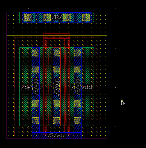
When creating a multi-fingered transistor schematic, in the Edit Instance Properties  window, there is an option for connecting S/D/G terminals. By checking that option, the corresponding layout creating via Layout Suite XL connective > generate all from source, indeed generate the multi-fingered transistor by connecting the sources and gates as instructed but it connects it in the wrong direction.

Has anyone used this option before and is there any way to change the direction? In this picture it should connected the top sources and the bottom gates.

Thanks

Version: Cadence Virtuoso  C6.1.8-64b.500.1

 1

FSDB support in Results Browser / ocean openResults() function

$
0
0

Hello,

  I'm trying to load some fsdb files using openResults in SKILL or through the Results Browser. I see older Virtuoso versions do not support this format (e.g. 6.1.6, some older 6.1.7 versions), but newer ones work ok.

   I would like to know which Virtuoso versions have support for this format and if the support is limited only to certain fsdb versions. Where could I find this information?

Convergence error working with compMacro model from the functional library

$
0
0

I was trying to simulate a circuit using "compMacro" instance in a simple test-bench using spectre (sub-version  IC6.1.8-64b.500.3 ").

However, in any simple configuration, also as mentioned in the user guide, I receive "Convergence error" 

I have included the functional library properly (it works for other instances from the library), but a simple DC or Transient analysis will not converge. The model has the default values but yet It is not working.


ERROR (SPECTRE-16385): There were 7 attempts to find the DC solution. In some of those attempts, a signal exceeded the blowup limit of its quantity. The last signal that failed is V(X0.2) = -3.01172 GV, for which the quantity is `V' and the blowup limit is (1 GV). It is possible that the circuit has no DC solution. If you really want signals this large, set the `blowup' parameter of this quantity to a larger value.
ERROR (SPECTRE-16080): No DC solution found (no convergence). 

Standard cell Import issue (spice to schematic) using Spice In import

$
0
0

Hi,

I try to create the schematic views of Standard cell from the spice file I have (spicefile.spi). However when I do the import the width and length of the device do not follow, and the device in the schematic have a default width and length value instead of the one specified in the spice file.

Here is below an example for one gate of this spice file:

.subckt AN2D0 A1 A2 Z VDD VSS
M_u3-M_u2 Z net6 VSS VSS nch3 w=0.58u l=0.35u
M_u2-M_u4 X_u2-net6 A2 VSS VSS nch3 w=0.58u l=0.35u
M_u2-M_u3 net6 A1 X_u2-net6 VSS nch3 w=0.58u l=0.35u

I used the desig map file as below:

-- Device Mapping file generated from SpiceIn GUI
devSelect := nch3 nmos3v
    propMap := wf w

devSelect := pch3 pmos3v

propMap := wf w

Do you please have any idea to fix this import issue?

Thank you,

Best Regards

KC


Accessing temperature in an AMS simulation

$
0
0

In Spectre, you can assign a "temp" to a voltage source, and access the simulator temperature as a voltage, but this doesn't work in AMS. Is there a way to do something similar in AMS, to access the current temperature from the simulation?

how to set libmanager open automatically as ciw

$
0
0

Hi,

Is there anyway to set libmanager open automatically as ciw when cadence is starting ?

Thanks

ERROR: The subckt `NMOS_X' is being redefined

$
0
0

Hello,

During a corner simulation with technology XFAB xs018, I get the below mentioned error:

The subckt `NMOS_X' is being redefined. Previously, it was defined in line 24 of `model_file_path'. Remove or rename either definition.

In my understanding the corner setup need to be vrified. Hoping for a quick solution. Can you suggest some alternatives?!

I am using Cadence Virtuoso 6.1.7

Thanks and Regards,


how can I hierarchically place the flatten top level

$
0
0

Hi,

Let me explain this with some example. I have a design say top-level that instantiate 4-instance of B along with bunch of other cells. There are two ways to do the placement using layout-xl:

i) Flatten the complete layout at top-level and do manual placement of each cell. Too much repetitive work and looses consistency between different instance of B

ii) Do placement at level B then from top-level instatiate B along with other cells. Saves times roughly by 4 since only once B instance and then some other cells to be placed. All B-instances are consistent. But I see area inefficient because there are lots of empty space in B that I can put some from top-level had the placement done flat.

So my question is related to (ii), is there a way to do hierarchical placement of instances so that they are all consistent and then flatten them that way we can make use of the empty space in the instance.

Satendra

How to protect the PDK files?

$
0
0

Hello guys,

I would like to ask a question about the protection of PDK files:  display.drf, 018cmos.rul, 018cmos.tf, and so on. I have tried the ncproctect which works well with veriloga file, but not with these mentioned files. Thanks in advance.

Best regards,

UU

Display controls for path and vias

$
0
0

Sorry if this is a redundant question... 

There's somewhere, an option that changes the way paths are displayed when being drawn and vias are displayed 

when being placed... 

Any hints would be appreciated!

Decap Cells

$
0
0

How does insertion of Decap cells results in increase of leakage power?

Do I delete my PVT data via Re-run Unfinished/Error Points in ade-xl

$
0
0

I have a transient simulation of 128 PVT corners done with last 10 corners are somehow not simulated. It's saved under interactive,0. Hence I press the button called "Rerun unfinished/Error Points" in history tab of ade-xl. There is a new simulation created called interactive.0.rerun. However, somehow, it failed to execute again. So I just delete this data called "interactive.0.rerun", but later I find all the data in interactive.0 cannot be plotted. I try to open the psf files in Results browers and not sure how to plot them all.

My question is do I accidently delete all the PVT data because they have been transferred to the simultion of "interactive.0.rerun" after I click the button "Rerun unfinished/Error Points". If they have not been deleted, how to recover it ?

Viewing all 4891 articles
Browse latest View live


<script src="https://jsc.adskeeper.com/r/s/rssing.com.1596347.js" async> </script>