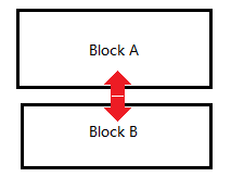
I have a requirement to short-circuit 512-bit signals every 8 bits and then send them to the next circuit module for current detection, as shown in the figure below. After carefully reading Chapter 2 of the "Virtuoso® Schematic Composer Tutorial" manual, I found that such operation is not supported. I thought of designing a symbol called "8current_to_1current" to achieve this operation. I have thought of two solutions:
- For the first solution, it seems that currently, I can only connect a device (e.g., a 0-ohm resistor) to each bit. On the layout, according to the solution provided by the experts earlier[post title: update the layout connectivity by shorting two terminals of Analog lib Resistor in layout - Custom IC SKILL - Cadence Technology Forums - Cadence Community], I can use the "Remove Device entry” to (short(PLUS MINUS)). By doing so, the layout issue indeed shorts the resistor, but it seems that LVS cannot pass. Is there a solution to make LVS pass as well? In this post whose question is similar to me[post title: How to properly short together named nets for schematic and layout], someone mentioned that metal resistors can be used to replace the resistors, so that the layout also has metal resistors. Unfortunately, the PDK I am using does not have the layout of metal resistors.
- For the second solution, I think it should be feasible, but when I need to short-circuit every 32-bit signal for current measurement, this will become very cumbersome.
- There's another post [post title: connect all the bus lines together - Custom IC Design - Cadence Technology Forums - Cadence Community] that seems similar to my question, but in their circuit, there's capacitive charging after, whereas mine involves direct short-circuiting.
![]()


 and
and 


