Quantcast
Channel: Cadence Custom IC Design Forum
Viewing all 4891 articles
Browse latest View live

Rotate schematic component without rotating the component labels?

$
0
0

When I rotate a component in the schematic view, the labels are rotated too e.g. rotating by 180 degrees will leave the text upside down.

I know I can rotate each text field back manually but that is tedious.

Is there any way to fix the orientation of component text?


PSTB loop-gain Phase-plot : error at lower frequency

$
0
0

Hi.

I am simulating the common-mode loop gain of common-mode feedback loop of a fully differential amplifier, through PSS/PSTB analysis (using "diffstbprobe").

But, the phase-plot obtained shows a low-freq (dc) phase of 0° (instead of 180°) !

Please see the attached screenshot - the left half phase plot is as expected (obtained from another circuit), but the right half plot seems erroneous at low frequencies as I stated above!

I am using: PSS errpreset=conservative, and reltol=1e-5, vabstol=3e-8, iabstol=1e-13.

Can you please suggest a way to obtain the actual phase plot profile from the PSTB.

PSTB plots

Thanks!

save DC operating points in ADEXL

$
0
0

Hi,

I wonder how I can save the DC operating points in the output window and have the valued displayed after I run simulations for different corners.

When I use ADE, after the DC sim, I can choose "Annotate - DC operating points", then the net voltage will be displayed in the schematic. Is there a way I can put a certain net voltage into the output window so that the results will be displayed automatically after the simulation is done?

I need to check some voltage and current over different corners, so I'll need to add them into the outputs.

I tried to put OP("/xxx" "i") in the output, but it does not do anything.

Any help is appreciated. Thank you very much! 

Copying A Maestro View and underlying schematics to a new library

$
0
0

Hi,

Can anyone help me find a solution to this please?

- I am using ADE Assembler and the Maestro database format.

- I have a Cell which has its own Maestro View, it resides in Library A.

- Inside the Maestro View there are a number of different tests, each referencing a different Testbench schematic containing different DUT's.

- All of the DUT schematics and Testbenches called by the Maestro view exist inside Library A. Anything else from outside of Library A can just be referenced and not copied (e.g. logic cells).

- I want to copy my Cell from its current location into a new library.

- I want the copy to automatically pick up all the TB's and schematics used inside the maestro view from Library A and copy them to Library B, and have the Maestro View update pointers to Library B for these TB's and schematics accordingly.

I have tried:

- Using the right click copy options on the cell

- Copy Wizard

Both of the above on ADEXL views (ADEXL views DO copy as expected using above methods)

Thanks!

Craig

Variable instance number and bus width depending on CDF parameter

$
0
0

Hi all.

I want to create a variable number of instances and bus width dependent on a CDF parameter. In the same way that multibit instance from analogLib does!

How could I get it?

Thanks!

Transient Noise Simulation for Different input/output frequencies

$
0
0

hi

I am using virtuoso version IC6.1.5.500.16.2. I made a demodulator (60GHz Carrier , 20Gbps data rate) and trying to compare its output eye diagram with/without noise. 

I am using transient noise simulation and enabled the noise from frequency 40G (fmin) to 80G (fmax) with seed of 128 (seed is 128 because modulator has a PRBS source with 128 seed value).

By these values i am enabling the (white noise from 0 to 40G) + (white and pink noise from 40G to 80G) for the demodulator input signal.

But demodulator output signal  is 20G base band. How can i activate the noise (pink noise) for the output circuit elements which are dealing with 20GHz base band signal?

If i choose Fmin = 1Hz and fmax = 80GHz it enable white + pink noise from 1 to 80GHz but adds out band noise at the input of demodulator which is not desirable.

kindly give your valuable suggestion.

thanking you in anticipation

zubair

note: for transient noise simulation setup i studied the cadence document ""Application Note on Direct Time Domain Noise Analysis using Virtuoso Spectre"

ADE XL Timed Out Running Monte Carlo Simulation

$
0
0

This is the first time we are trying a Monte Carlo Simulation so it is most likely a setup issue but I'm not sure where to look for additional clues.

We are able to run a 'Single Run' simulation of a simple circuit using ADE XL but when we try to run Monte Carlo Sampling of the same simple circuit we get

error ADEXL-2107  Job timed out while pending after 300 seconds

and the run status says 'running' but it never starts/finishes. 

What to try and where to look for additional clues ?

thanks

multipart path - automatically fill path width with rows of subrectangles

$
0
0

Is there a way to have the MPP automatically determine the number of subrectangle rows as a function of master path width?


how to use variable in parameter sweep

$
0
0

I want to transfer the expression result (X) in test A to test B by calcVal function.  Then I wish test B to run transient simulation using parametric sweep based on X, e.g., from X-2, X-1, X, X+1 and X+2. However, cadence say it can't use variable to define sweep range. Is there any solution to do this kind simulation ?

The tool I am using is IC617. 

Best regards

Measurement of delay between change in value of two buses created using Analog to Digital function

$
0
0

Please refer to the waveform shown in the attached screenshot.

bf_idx0_d1_o<31:0> is a bus where all the bits transition from high to low or low to high at roughly the same instant of time. However there is a slight spread in the exact time when each of the individual nets transition. This results in the 'digital' value of the bus obtained after Analog to Digital Conversion to toggle for some time before settling to a final value.

In my calculations I need to measure the time from the instant the bus reaches a stable value to the instant when a single bit output signal (op_ko) toggles in the same high-to-low or low-to-high direction. 

If I use the delay function in the Visualization and Analysis XL calculator, it gives me the time from when any of the bits of the bus first cross the threshold value. The formula I am using is

awvCreateBus("bfidx0" list(awvAnalog2Digital(v("/bf_idx0_d1_o<0>" ?result "tran") nil nil 0.5 nil "centre") awvAnalog2Digital(v("/bf_idx0_d1_o<1>" ?result "tran") nil nil 0.5 nil "centre") awvAnalog2Digital(v("/bf_idx0_d1_o<2>" ?result "tran") nil nil 0.5 nil "centre") awvAnalog2Digital(v("/bf_idx0_d1_o<3>" ?result "tran") nil nil 0.5 nil "centre") awvAnalog2Digital(v("/bf_idx0_d1_o<4>" ?result "tran") nil nil 0.5 nil "centre") awvAnalog2Digital(v("/bf_idx0_d1_o<5>" ?result "tran") nil nil 0.5 nil "centre") awvAnalog2Digital(v("/bf_idx0_d1_o<6>" ?result "tran") nil nil 0.5 nil "centre") awvAnalog2Digital(v("/bf_idx0_d1_o<7>" ?result "tran") nil nil 0.5 nil "centre") awvAnalog2Digital(v("/bf_idx0_d1_o<8>" ?result "tran") nil nil 0.5 nil "centre") awvAnalog2Digital(v("/bf_idx0_d1_o<9>" ?result "tran") nil nil 0.5 nil "centre") awvAnalog2Digital(v("/bf_idx0_d1_o<10>" ?result "tran") nil nil 0.5 nil "centre") awvAnalog2Digital(v("/bf_idx0_d1_o<11>" ?result "tran") nil nil 0.5 nil "centre") awvAnalog2Digital(v("/bf_idx0_d1_o<12>" ?result "tran") nil nil 0.5 nil "centre") awvAnalog2Digital(v("/bf_idx0_d1_o<13>" ?result "tran") nil nil 0.5 nil "centre") awvAnalog2Digital(v("/bf_idx0_d1_o<14>" ?result "tran") nil nil 0.5 nil "centre") awvAnalog2Digital(v("/bf_idx0_d1_o<15>" ?result "tran") nil nil 0.5 nil "centre") awvAnalog2Digital(v("/bf_idx0_d1_o<16>" ?result "tran") nil nil 0.5 nil "centre") awvAnalog2Digital(v("/bf_idx0_d1_o<17>" ?result "tran") nil nil 0.5 nil "centre") awvAnalog2Digital(v("/bf_idx0_d1_o<18>" ?result "tran") nil nil 0.5 nil "centre") awvAnalog2Digital(v("/bf_idx0_d1_o<19>" ?result "tran") nil nil 0.5 nil "centre") awvAnalog2Digital(v("/bf_idx0_d1_o<20>" ?result "tran") nil nil 0.5 nil "centre") awvAnalog2Digital(v("/bf_idx0_d1_o<21>" ?result "tran") nil nil 0.5 nil "centre") awvAnalog2Digital(v("/bf_idx0_d1_o<22>" ?result "tran") nil nil 0.5 nil "centre") awvAnalog2Digital(v("/bf_idx0_d1_o<23>" ?result "tran") nil nil 0.5 nil "centre") awvAnalog2Digital(v("/bf_idx0_d1_o<24>" ?result "tran") nil nil 0.5 nil "centre") awvAnalog2Digital(v("/bf_idx0_d1_o<25>" ?result "tran") nil nil 0.5 nil "centre") awvAnalog2Digital(v("/bf_idx0_d1_o<26>" ?result "tran") nil nil 0.5 nil "centre") awvAnalog2Digital(v("/bf_idx0_d1_o<27>" ?result "tran") nil nil 0.5 nil "centre") awvAnalog2Digital(v("/bf_idx0_d1_o<28>" ?result "tran") nil nil 0.5 nil "centre") awvAnalog2Digital(v("/bf_idx0_d1_o<29>" ?result "tran") nil nil 0.5 nil "centre") awvAnalog2Digital(v("/bf_idx0_d1_o<30>" ?result "tran") nil nil 0.5 nil "centre") awvAnalog2Digital(v("/bf_idx0_d1_o<31>" ?result "tran") nil nil 0.5 nil "centre") ) "Binary")

and the value I get is 238 ps at 4.235 ns. You will however see in the figure that the bus actually stabilises at 4.3 ns.

How do I modify the formula to get this functionality.

If the screenshot is not visible in the post, I have also uploaded it to my public Dropbox here

https://www.dropbox.com/s/3njgofoda3cfajt/delay_measurement_virtuoso.JPG?dl=0

Regards,

Prashant

CDF instance information warning meaning

$
0
0

Hello all,

Can someone please tell me the meaning of this warning message:

*WARNING* Unable to set cdf instance information for the master cellView of instance M0 does not have a master.

Thanks

Display current view in window title bar

$
0
0

Hi,

Is there a way to have the window's title bar display the current view?

I ask because we use Keysight's Momentum with Virtuoso and it keeps a separate layout view which is essentially identical to the standard layout.

The issue is that there is no way to tell which view is currently open when you have two layout (one "layout" layout view, one "momentum" layout view) views open at one time.

Is there a way to enable this?

Parasitic exclusion

$
0
0

Hello,

I was using parasitic filter from an extracted view to discover the worst influences. I understood that I could add some parasitics or include all parasitics of an extracted view. So, if I want to simulate my circuit with all parasitic excluding a net, I have to include all parasitics in my constraint window and deactivate the one I don't want. Logic. But, it would be more simple in this case, by default activating all parasitics (without including the long list of parasitcs) and only put in my constraint window the net I don't want the parasitics.

Is it possible?

Emmanuel

calibreview fatal error

$
0
0

After I use calibre PEX for extraction, and it finishes without errors, I want to import the netlist created into a Cadence schematic with calibreview. However, when I run calibreview, I get a fatal error message, telling me to  consult log file. The logfile contents are below

INFO: cds.lib has been converted to lib.defs /opt/CoE/mentorGraphics/aoi_cal_2017.2_28.22/tmp/32702_result_lib.defs

RUNNING PEX back-annotation...

//  Calibre FDI  v2017.2_28.22 Tue Jun 6 14:24:00 PDT 2017

//

//                  Copyright Mentor Graphics Corporation 2008-2017

//                             All Rights Reserved.

//         THIS WORK CONTAINS TRADE SECRET AND PROPRIETARY INFORMATION

//             WHICH IS THE PROPERTY OF MENTOR GRAPHICS CORPORATION

//               OR ITS LICENSORS AND IS SUBJECT TO LICENSE TERMS.

//

//  Mentor Graphics software executing under x86-64 Linux

//  64 bit virtual addressing enabled

//

//         This software is in pre-production form and is considered to be

//         beta code that is subject to the terms of the current Mentor

//         Graphics End-User License Agreement or your signed agreement

//         with Mentor Graphics that contains beta terms, whichever applies.

//

//  Running on Linux engr-icms06g.catnet.arizona.edu 3.10.0-693.5.2.el7.x86_64 #1 SMP Fri Oct 13 10:46:25 EDT 2017 x86_64

INFO: Parsing command line arguments...

INFO: License checked out successfully for calibreqdb.

INFO: Parsing cellmap file...

INFO: Executing back annotation...

ERROR: Could not access LibDef plug-in for oaLibDefSystem: #4: Shared Library Not Found: Error loading library 'libddbase_sh.so'. /opt/CoE/cadence/IC617/tools.lnx86/lib/64bit/libddbase_sh.so: undefined symbol: _ZN8oaCommon11FactoryBase11getRefCountEv

It seems like there is an issue with 'libddbase_sh.so'? I assume this is a file needed by cadence? The virtuoso version is

virtuoso version 6.1.7-64b

Calibre Skill Interface * (v2017.2_28.22) *

How to simulate pnoise of fractional (non-integer) frequency divider

$
0
0

Hi there,

I tried to simulate pnoise of the frequency divider with a divider ratio of 4.5 (non integer value). however, I have a hard time in setting the beat frequency to be Freq_in/4.5 with relative harmonic = 1, as it complaints about the fundamental tone (=Freq_in) must be integer multiple of beat frequency. The cadence version that I use is ICADV12.3 and MMSIM version is 16.1.0.479.isr9.

Thank you in advance for all your replies.

Yin


Next line continuation in cds.lib

$
0
0

Hello,

I have long lines of libraries assigned to a combine category and reading them in cds.lib is difficult. 

I would like to continue the command in the next line but I am not sure what character can mean the line is continues in the next line for the library manager.

\ or + didn't work. 

Any suggestions?

Thanks,

Ali  

Jumper, Simulation MUX etc

$
0
0

Hi,

How to I best implement a "jumper", MUX or switches for simulation time?

Often, I want to avoid creating new testbenches for every single purpose.

Example: I have an LO input and for certain simulations I want to DC couple a bias voltage through an inductor. But in other scenarios, this inductor should be disconnected. On a PCB, I can implement this with a 2x2 header that I jumper properly.

In Cadence so far I always manually remove the wire connection which is a pain.

What I envison is a MUX (or similar) with multiple inputs and based on a CDF parameter (that eventually I set in the ADE L window as design variable) one connection is routed through and the others disabled.

Thanks!

running simulations on dedicatede SSD drive

$
0
0

Hi,

We are running fairly large simulations/extractions/LVSs in our lab (100s'-k components, RLCK). One of the key limiting factors of our simulation speed was that our data is sitting on a university file server (if I understand this correctly). Our simulation machine fetched the files from the file-server for processing so no only simulation speed suffered, the communication of other users with the file server was clogged as well. We already noticed that by running our simulation locally (i.e. in simulation directory set ../tmp in stead of ./simulation), speed and traffic SIGNIFICANTLY improved.

The question is whether or not setting our local simulation directory on an SSD will further accelerate performance.

Our typical local machine is 16/32 physical/logical cores, 2.6GHz processors with 512GB RAM, running IC616 (latest hotfix).

Any insights will be much appreciated,

Thanks ahead,

Matan

Measurement of ground bounce and impedance of RLC network

$
0
0
Hi all, 

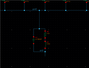
I am trying to measure the effect of power gating on the substrate noise. In other words, I want to measure the amount of ground bounce through SPICE simulation. Initially, I am planning to use lumped RLC model (attached picture) to mimic the ground network. 

Now I have two questions: 

1) Is that the correct approach to measure the ground bounce? If not what are the methods/metrics I should use? 

2) I also want to measure the impedance of the power distribution network using this lumped RLC model for different switching activity of load circuits. I am not quite sure how to achieve this. For example: how can I get impedance vs frequency characteristics using the lumped RLC model I am using? 

Please let me know if you have any question. 

Thank you for your time and help.

Quarter-Circle in Layout without converting to polygon

$
0
0

How can I create a quarter circle in layout that doesn't get converted to polygon?

I tried creating a full circle and chopping. But, as soon as I chop it gets converted to a 20-sided polygon.

Viewing all 4891 articles
Browse latest View live


<script src="https://jsc.adskeeper.com/r/s/rssing.com.1596347.js" async> </script>