Hi,
I made a charge pump for 1GHz PFD up and down signal pulses. I am interested in finding out the gain of Charge Pump. Can anyone guide me the good reference or some idea about its procedure?
Thanks,
Hi,
I made a charge pump for 1GHz PFD up and down signal pulses. I am interested in finding out the gain of Charge Pump. Can anyone guide me the good reference or some idea about its procedure?
Thanks,
It is a very simple question, it seems that I can't change an instance name by "q" it in schematic window. I have to go to the property editor and change it there. For instance, I placed a resistor R1 in the schematic and then later I want to change it to R1<2:0>. Naturally I want to q it and then change it there. however, the instance name field is grey. Instead, I have to change it in the property editor. For some reason, changing things in the property editor can be annoying. I click in the field that I want to change, sometimes when my cursor moves, then immediately the edit mode is gone, I have to click again and again. I don't know why it is happening.
Is there a way that I can edit the instance name by q it in schematic, or how can I fix the input issue in the property editor? I am using IC617.
Thanks!

Hi, Andrew
I have checked the gpdk045 model report, it's said the vth is obtained using constant current method, the intercept current=Icon*W/L (Icon=1e-8A for 1.1V device and Icon=1e-7A for 1.8V device), Vth unit is V, spec is here
and i simulated use the circuit, VDS=1.1V and sweep the VGS from 0 to 1.1V.

according to the equation constant current method int current = 10u/40n *1e-8A =2.5*e-6 A =2.5uA, check the ids and vth is located at around 320mV, close to the spec, but check at result browser, plot the vth, about 620mV, what is wrong here? thanks a lot.

I am running high-yield estimation (HYE) simulation for custom SRAM design in Virtuoso 6.1.6 ADE XL. The simulation circuit is a critical path which contains representative cells and wire delay models to mimic 512Mb SRAM macro. We do not run a simulation directly on the 512Mb SRAM macro to avoid highly long run-time.
In HYE setup, we need to specify the sampling number for Scaled-sigma sampling (SSS) method. According to Cadence technical paper, the default number of samples for SSS is 7000.
The problem is, the 512Mb SRAM macro has millions of devices while the critical path has only hundreds of devices. When we run HYE on the critical path, we expect that the hundreds of devices' variations could mimic millions of devices' variations in some way. Assume that the default 7000 sampling number is appropriate for 512Mb SRAM macro's HYE simulation, then what sampling number is adequate for the critical path HYE simulation in order to mimic millions of devices' variations?
Actually, I am not even sure if the default 7000 sampling number is adequate when running HYE simulation directly on the 512Mb SRAM macro.
I appreciate any suggestions on this problem. Thanks and regards.
Hi,
I am doing custom layout in Virtuouso & and for that purpose, I'll define some designs (as per standard cell rules) and instantiate them in the upper level layouts.
Now, when I instantiate any design in layout, I need to manually align their PR boundary for the neighboring cells.
Is there any way to automate this PR boundary aligning process in Virtuoso?
Any help will be greatly appreciated.
Our company is doing MEMS design. Several years ago, when we started, we decided to use IC 5.1.41 and I have modified the technology ( TSMC 180nm) to include the needed layers. Now, we want to start new projects ( and eventually move the old ones) to IC 6. Things are a little more complicated in IC6 and I am having problems doing the same modifications.
The way I tried to do it is by dumping the original techlib, adding the new layers and recompiling it. I thought I was using available layer numbers for the extra layers, but each one of them is rejected as "reserved" during compilation. I have read that there may be several level of tech databases in IC6. The one I can see is the cdfDefTechTechLib, but the layers I tried to use are not there.
I have a few questions:
- what is the way to see all the databases chained in the techlib ?
- how can I find and eventually change the reserved layers?
- IC5 had the utility to edit the layer purpose pairs without having to recompile the whole tech library. Is there something similar in IC6
- what is the best way to replace an existing layer ( that I believe it is not used for our designs in the techlib) with another one?
Thanks a lot,
Mugurel
Hello!
I run my simulations in a /tmp/ folder in our server, that is weekly cleaned, and I copy the meaningful results in my local folder. So, the Result Directory Location in ADEXL is set to the tmp folder.
Now, I want to open ADEXL and use Direct Plot-> Main Form with the saved data in the local folder, not the /tmp/ one. Is there a way to do that?
Thanks a lot!!
I usually leave it at default while constructing circuit in Cadence Virtuoso. I didn't really understand what it is or why it is used for.
In Global Model files section I have NN, SS, SF, FS, FF , etc. in drop down list. What does that mean?

Hi All,
Here is my tool info:
Virtuoso ICADV12.3-64b:
Here is the Screenshot of the MarkNet Options forum:

We use MxCUT mask1 as a STOP layer for Mx mask1 metal. (x=0-3). Similar to MxCUT mask2 and Mx mask2.
As highlighted in red, we can add color & lock options only for Layer. There is no provision to add color & lock options for STOP layer.
Because of this issue, when I highlight a mask 2 M0, it stops at mask1 M0CUT. Same highlight issue between mask1 M0 and mask2 M0CUT. Similar for all Mx metals.
It would be really helpful if there is an option to add color & lock for a STOP layer in markNet Options form. Is there any work around or other solution to this problem? Any Skill Code?
Thanks in Advance.
Baig
Hello
I designed a foot print for a connector" The suggested footprint looks like the one below. This connecteur only have 2 positions, so this means 2 pads are electrically connected.
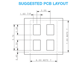
on my layout on Orcad PCB editor, i designed one as being the electrical pin and the other one being the mechanical one. The idea is that when I connect the line, i can start from one or the other pad, and the software will know the pin is connected. unfortunately, I cannot connect a mechanical pad, and i cannot design a pad with 2 shapes.
how am I supposed to do it?
Thanks a lot
I'm trying to understand what options, if any, I might have for controlling what different combinations of layers, widths, and spacing are used in a "Techgen -simulation" run. This is EXT17.12. Also if I am only planning on running Quantus-FS (field solver mode) and not the "full chip" mode (QRC), is there a way to dramatically speed up the Techgen -simulation stage?
I'm currently running:
Techgen -simulation -multi_cpu 8 -cell_off myprocess.ict
so far what I'm seeing is I wish I had the hardware to make that 8 about 128!
Thanks
-Dan
Hello all,
this is just a curiosity, but it has been tormenting for a while.
Sometimes, when a colleague of mine opens an ADE-XL view, ViVa also opens, showing the last waves that were plotted.
Sometimes, this does not happen.
On my workstation, this happens much rarely and I have been not able to reproduce this or find a root cause.
My colleagues would like ViVa to _never_ open when they open an ADE-XL view.
Which settings control this behaviour?
Thank you and best regards,
Patrik
Hello,
I have spent a lot of time investigating following task:
Assume I have to perform mismatch simulations of a comparator using montecarlo anlaysis in ADE-XL. I need to collect comparator offset (dc sim) and duty cycle ( tran).
As a result I would like to have a scatter plot where on X-axis offset voltage and on Y-axis duty cycle.
I have tried several methods but without any success.
Apporach 1: I have one test withe two instances of the comparator (I1/ I2). I have a dc /transient simulation preset in single test.
Comparator I1 has stimuli for dc offset extraction, while I2 has stimuli for transient analysis ( duty cycle extraction).
 I have specified instance as "Master" of CMP_TOP cell in montecarlo "Specify Inst/device" menu.
As a result on line has been created for test:
| Test | Type | Sch/Master/Subcircuit | Data |
| tst | Master | CMP_TOP | I1, I2 |
I have checked mismatch data applied for devices inside the comparator but only to see that a different set of values have been used for I1 and I2. I have looked for every possible option/setting but no way where I could specify correlation between the devices in I1 and I2.
I know for a fact that when you are defining parameter distribution for montecarlo there is a statistic block where a special syntax exists that allows to define correlation between devices/parameters.
Mismatch Correlation (Matched Devices)
The syntax of the instance or mismatch correlation statements are:
correlate dev=[list of subcircuit instances] {param=[list of parameters]} cc=<value>
correlate dev=[<wildcard_expression] {param=[list of parameters]} cc=<value>
Approach2: create 2 separate test benches + schematics and then use the same method to specify device for mc variation. Just a note that the instance name will have to be exactly the same otherwise different set of variations will be used for each setup.
I am using IC617ISR15 and MMSIM 16.1.
Question1: Is there a way in MC setup how achieve that a any occurrence of a cell inside the test bench schematic will end up having the same statics parameter variations within single mc simulation run?
Question2: Assuming I will have two test benches where the offset will be expression calculated in test1 and duty cycle in test 2. How to make a scatter plot in montecarlo sweep where on x-ais will be expression value from one test and on Y-axis value of an expression from another test?
Many thanks!
Regards Marian
Hi,
I am simulating an oscillator with 8-bit trimming ability. An variable "TRIM_CODE" is defined as a decimal value then I use equations to define binary code from D7 to D0, which can be calculated from TRIM_CODE. In test bench, there are 8 vdc, each dc = Di*VDD, Di= D7...D0.
I try to sweep TRIM_CODE in PSS sweep, e.g., 97 to 101. However, the final result shows that PSS can not recognize 97 to 101. It only use the default value of TRIM_CODE to run PSS.
Any idea about this question ?
BR
HI ,
Is there anyway to execute skill command on a sequential manner?
Like while one command is getting executed, virtuoso will wait. Once execution is completed it will move on to command.
can ipcBeginprocess/ipcwait be used for this purpose?
Regards
Anand
Hello,
today I am facing an odd problem. Depending on the max job number and the number of points, some netlists are generated after a while, when the associated job is ready to run.
Problem is that, meanwhile, someone changed a symbol and some simulations finished correctly and others died due to a "netlisting error".
Is there a way to force ADE-XL to generate all netlists immediately?
I am using Virtuoso ICADV 12.3.500.15.
Thank you and best regards,
Patrik
Hi,
I am running a dc simulation using Spectre, the simulation is very simple, I am just using and Ideal dc supply from the analogLib to pump a certain DC current in the drain of a transistor and I repeat the test for different transistors (mainly different sizing).
What I don't understand is why when I am trying to report the dcOpInfo parameters (either Id or Ids) I always see a small error delta for some specific instances, although they all have the same current going through them from an ideal supply ?
Tolerance options are set to default : reltol: 1e-3 Vabstol:1e-6 iabstol:1e-12
Example below for Ids = 5uA and 10uA
M12_135n/M0
id = 5u ids = 5u
/M3_36n/M0
id = 5.005u ids = 5.005u
/M4_135n/M0
id = 5.002u ids = 5.002u
/M4_36n/M0
id = 5.006u ids = 5.006u
/M4_72n/M0
id = 5.007u ids = 5.007u
/M4_8n/M0
id = 5u ids = 5u
/M12_135n/M0
id = 10u ids = 10u
/M8_72n/M0
id = 10.01u ids = 10.01u
/M8_8n/M0
id = 10u ids = 10u
Best Regards
I've been looking in to how I can get multiple machines involved in a Techgen run. I read the DPL User Guide and it suggests some command line utilities for verifying the DPL config file (dplCfgValidator) and for testing the cluster (dplDiagCmdUtil). However, when I try either of these I get a "DPL applications required Run DPL using a application" message. I can't see where the manual says anything about this.
> /opt/eda/cadence/EXT171/bin/dplCfgValidator -ConfigFile dp_config.xml
DPL applications required Run DPL using a application
>
Here is a version:
-----------------------------------------------------------------
Name : dplCfgValidator - Cadence DPL Engine - (64-bit)
Description : Cadence Shared Technology for Distributed Computing
Version : 8.3.3-a001
Build Ref. No. :
IR Build No. : Engineering build
Build Date : (01/19/2017 19:46:16)
-----------------------------------------------------------------
The other thing which wasn't clear in the manual was the relationship between <Host> tags in the XML DPL config file and the -dp_num command line argument. Is there a way to tell the tool "just use all of the hosts" or do I need to count my hosts and use that as the argument to -dp_num? The other thing which wasn't clear is the DPL config file lets me specify a number of jobs per host like:
<Host instance="8">host1</Host>
<Host instance="4">host2</Host>
so in this case do I use -dp_num 2 (for two hosts) or do I use -dp_num 12 (to get all slots on all machines)?
If it matters, I'm using <DPLEnvironment type="ssh">
Hi ,
Is there any way to generate itf file from ict file ? I could see there are some cadence utilities for conversion of itf to ict but i couldnt find the other way around.
Thanks
Anand
hi
I ran two simulations separately to compare the output of two circuits (Both circuits are in same library with different cells but nodes names are similar). I cannot compare the two results as only the last ended simulation results are available against both net name.
How can i store the results with same net names of two different cells? (actually its hectic in my test setup to assign different net names)
Thanks
zubair