Is there an environment variable I can use in my .cdsinit that sets the default simulator to Spectre X?
↧
Set default simulator to Spectre X
↧
maestro - AMS simulation - IE Card setup - tolerance/simulation error
Hi,
I want to simulate a mixed signal design, with one cell on transistor-level and other cells as verilogams/vhdl models, with high accuracy (<2µV error).
One cell (called S2D) is modeled in verilogams, and is stimulated with an vsin source, and should convert the input stimulus to a wreal-value for further calculations in verilogams.
However, during simulation, I've noticed that the input is wrong, and the wreal-value does not match the analog value.
In the IE card setup, vdelta is set to 2u.
In the plot below, the interface element (input: analog voltage, output: wreal value) for the S2D input is shown.
In >90% of the transient simulation, the output (Dout, wreal) is equal with the Input (Ain, voltage) within the tolerance of +-2u.
However, there are some points where the difference is far too big, in the plot below for example 1,4mV!
Are there any other settings that affect the tolerances of the automatically inserted Interface elements?
Simulator is AMS, errorpreset conservative, Cadence Version IC6.1.8-64b.500.8.


↧
↧
Limit License usage (not number of jobs)
HI,
we have a limited number of simulation licenses for our users and we want to avoid to use up all licenses at a time.
Currently the user can only set the number of parallel jobs to run, but depending on the jobs analysis (Spectre, APS Base, APS RF, APS Multicore) a different number of licenses is checked out.
Is there a way to set the max. numbers of licenses per user ?
For example the user can set his limit to 10 licenses (e.g. for license: Virtuoso_multi_mode_simulation) ?
BR
Holger
↧
Liberate System error - could not execute command
I am working on characterizing some newly created standard cells and I keep getting the following error after the char_library is executed:
ERROR (LIB-5048): (LIBERATE): System error - could not execute command: cd /tmp/altos.lnissrv2.eng.utah.edu.T20201002102423635916S0030740.0; /uusoc/facility/cad_tools/Cadence/lnis_tools/SPECTRE191/bin/spectre +lqt 0 -outdir /tmp/u1249940/ =log sim.lis +lorder MMSIM:PRODUCT +spice =log sim.lis +libtkn 0001208F0F964DEB4DDB67C73FE609F74FDE77D55BF946F37BD5279610F747F509CF6EC154DA12934B9F70D7629B49EA4ECE0BD3368335D8109B25EB159644D65A996F953AED25A20AD079D119DF75F437E972DC5A8843920ED063D001D50190449B2D8705DC47920DD879D1288977A237E979D11B8977A237E926A64FB32398689E00003A6F /tmp/altos.lnissrv2.eng.utah.edu.T20201002102423635916S0030740.0/sim.sp >& /dev/null. Error code: 2.
*Info* Simulation failed to complete. Restart the simulation in 5 seconds on host lnissrv2.eng.utah.edu.
This is the log output file
community.cadence.com/.../char.log
I have copied that command from the terminal and run it outside of liberate and it seems to work fine, the sim.sp file is outputted to that directory specified.I am trying to change the locations of where to store the spectre files are outputted to along with command options for spectre by setting the extsim variables just as provided in the documentation but it is obviously not working. Any and all help will be appreciated, I am adding my scripts below for a complete explanation of the problem
I will be attaching my scripts below also:
char.tcl
set SRC_DIR [pwd]
set RUN_DIR [pwd]
set PROCESS tt
set VDD_VALUE 1.8
set TEMP 25
set LIB scs8ms_muxinv2_1
set TEMPLATE skywater_scs8ms_template
set SETTINGS_FILE ${SRC_DIR}/SETTINGS/settings.tcl
set TEMPLATE_FILE ${SRC_DIR}/template/${TEMPLATE}.tcl
set CELLS_FILE ${SRC_DIR}/tcl/cells.tcl
set MODEL_INCLUDE_FILE ${SRC_DIR}/MODELS/SPECTRE/include_${PROCESS}.scs
set NETLIST_DIR ${SRC_DIR}/NETLIST/SPECTRE
set USERDATA ${SRC_DIR}/userdata/userdata.lib
source ${SETTINGS_FILE}
source ${TEMPLATE_FILE}
source ${CELLS_FILE}
set_operating_condition -voltage ${VDD_VALUE} -temp ${TEMP}
puts "Specifying External Model"
set_var extsim_model_include ${MODEL_INCLUDE_FILE} ;#Define Model file to use
set_var extsim_flatten_netlist 1
set spectrefiles {}
lappend spectrefiles ${SRC_DIR}/MODELS/SPECTRE/include_${PROCESS}.scs
foreach cell ${cells} {
lappend spectrefiles ${NETLIST_DIR}/${cell}.scs
}
#Reading Spice Files
puts "Reading Spice Files "
read_spice -format spectre "${spectrefiles}"
#Initiates characterization, -extsim specifies to use an external spice simulator program
puts "Characterizing Library"
char_library -extsim spectre -cells $cells
#Writes a Liberate library database (.ldb) which will be read back later for formatting library data
write_ldb -overwrite ${RUN_DIR}/LDB/${LIB}.ldb
#Write the liberty file
write_library ${SRC_DIR}/LIBRARY/${LIB}.lib
cells.tcl
#Create List of all cells defined in the template file
#This file allows the user to redefine the $cells variable to quickly reduce the characterization size without editing the template file
set cells { \
scs8ms_muxinv2_1 \
}
template.tcl
# existing_templates.tcl : template Tcl file generated by Liberate 19.2.1.591 on Tue Sep 29 10:05:56 MDT 2020
#Identify power and ground nets and set their values
set_vdd -cells {scs8ms_muxinv2_1} -type primary vpwr 1.8
set_gnd -type primary vgnd 0
#-no_model used to specify if GND is not a net it is excluded from the Liberty file
set_gnd -no_model vgnd 0
set_var slew_lower_rise 0.2
set_var slew_lower_fall 0.2
set_var slew_upper_rise 0.8
set_var slew_upper_fall 0.8
set_var measure_slew_lower_rise 0.2
set_var measure_slew_lower_fall 0.2
set_var measure_slew_upper_rise 0.8
set_var measure_slew_upper_fall 0.8
set_var delay_inp_rise 0.5
set_var delay_inp_fall 0.5
set_var delay_out_rise 0.5
set_var delay_out_fall 0.5
set_var def_arc_msg_level 0
set_var process_match_pins_to_ports 1
set_var max_transition 1.5e-09
set_var min_transition 1e-11
set_var min_output_cap 0.0
define_template -type delay \
-index_1 {0.01 0.01735 0.02602 0.03903 0.05855 0.08782 0.13172 0.19757 0.29634 0.44449 0.6667 1.0 1.5 } \
-index_2 {0.0 0.00985 0.01182 0.01418 0.01702 0.02042 0.0245 0.0294 0.03528 0.04233 0.0508 0.06096 0.07315 0.08778 0.10534 0.12641 0.15169 0.18203 0.21844 } \
delay_template_13x19
define_template -type power \
-index_1 {0.01 0.01735 0.02602 0.03903 0.05855 0.08782 0.13172 0.19757 0.29634 0.44449 0.6667 1.0 1.5 } \
-index_2 {0.0 0.00985 0.01182 0.01418 0.01702 0.02042 0.0245 0.0294 0.03528 0.04233 0.0508 0.06096 0.07315 0.08778 0.10534 0.12641 0.15169 0.18203 0.21844 } \
power_template_13x19
define_cell \
-input { Q1 Q2 S } \
-output { Z } \
-pinlist { Q1 Q2 S Z } \
-delay delay_template_13x19 \
-power power_template_13x19 \
{scs8ms_muxinv2_1}
define_leakage scs8ms_muxinv2_1
# power arcs from => Q1 hidden
define_arc \
-type hidden \
-vector {Rxxx} \
-pin Q1 \
scs8ms_muxinv2_1
# power arcs from => Q1 hidden
define_arc \
-type hidden \
-vector {Fxxx} \
-pin Q1 \
scs8ms_muxinv2_1
# power arcs from => Q2 hidden
define_arc \
-type hidden \
-vector {xRxx} \
-pin Q2 \
scs8ms_muxinv2_1
# power arcs from => Q2 hidden
define_arc \
-type hidden \
-vector {xFxx} \
-pin Q2 \
scs8ms_muxinv2_1
# power arcs from => S hidden
define_arc \
-type hidden \
-vector {xxRx} \
-pin S \
scs8ms_muxinv2_1
# power arcs from => S hidden
define_arc \
-type hidden \
-vector {xxFx} \
-pin S \
scs8ms_muxinv2_1
# delay arcs from Q1 => Z positive_unate combinational
define_arc \
-vector {RxxF} \
-related_pin Q1 \
-pin Z \
scs8ms_muxinv2_1
# delay arcs from Q1 => Z positive_unate combinational
define_arc \
-vector {FxxR} \
-related_pin Q1 \
-pin Z \
scs8ms_muxinv2_1
# delay arcs from Q2 => Z positive_unate combinational
define_arc \
-vector {xRxF} \
-related_pin Q2 \
-pin Z \
scs8ms_muxinv2_1
# delay arcs from Q2 => Z positive_unate combinational
define_arc \
-vector {xFxR} \
-related_pin Q2 \
-pin Z \
scs8ms_muxinv2_1
# delay arcs from S => X positive_unate combinational
define_arc \
-when "(!Q1)" \
-vector {xxFR} \
-related_pin S \
-pin Z \
scs8ms_muxinv2_1
# delay arcs from B1 => X positive_unate combinational
define_arc \
-when "(Q1)" \
-vector {xxFF} \
-related_pin S \
-pin Z \
scs8ms_muxinv2_1
define_arc \
-when "(!Q2)" \
-vector {xxRR} \
-related_pin S \
-pin Z \
scs8ms_muxinv2_1
define_arc \
-when "(Q2)" \
-vector {xxRF} \
-related_pin S \
-pin Z \
scs8ms_muxinv2_1
↧
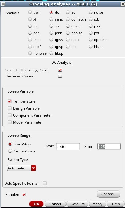
DCop inconsistency
I'm designing a low voltage BGR circuit and for the last 4 days i was getting non realistic results from cadence.
In the first 2 pics. I'm perorming a temperature DC sweep and i'm getting results that is not expected.
 community.cadence.com/.../1.txt
But if i sweep the temperature backwards (125 to -40) i get the results i'm expecting.

 community.cadence.com/.../2.txt
I can live with that problem. But there's a bigger one. The DCop that cadence give me when i ran at a specific temperature is from the wrong graphs. And I need to run AC and Transient analysis at the nominal 27 temperature.
↧
↧
"*.SCALE" is not supported. Use ".OPTION SCALE" instead
Hi
I am running the PVS LVS through the skill scripts and getting the below mentioned warning message on my unix terminal:
"WARNING (NVN-13003): "*.SCALE" is not supported. Use ".OPTION SCALE" instead or specify 'lvs_cdn_flow_options -cdl_use_scale' in the rule file."
While I run the LVS from the PVS GUI, I don't get this warning in the unix terminal, but lvs report file has this warning .
Could you please tell me that how to fix this warning message.
PVS version used: 19.12-64b, virtuoso: 6.1.8-64b
Thanks and Regards
Saurabh
↧
Noise circles, NC
Hi
Im using the NC function under SP analysis. But how do I get the frequency to be a variable. Normally, I would use VAR("frf") with frf being my deign variable.
Function: nc(getData("Fmin" ?result "sp_noise") gmin(getData("Gopt" ?result "sp_noise") getData("Bopt" ?result "sp_noise") zref(1 ?result "sp")) getData("NNR" ?result "sp_noise") '(1.0 1.1 1.2) '2.6e+09)
Thanks
↧
Aliasing net or shorting net of an extracted view
HI All,
I have a 3 terminal extracted view stitched in my schematic using a n2port. One of its terminal is GR
Is there a way I can alias this GR terminal of n2port with another net in my schematic so that they are connected like a short ?
I wish to connect the floating GR of the n2port to schematic gnd net.
regards
↧
Can two subcategories in the Library Manager have a different name?
Hello all.
Let's say that we have a library with the category foo and bar.
I want that the will be for these categories a sub-category "sim", but it should be a different group. I.e., cells from the sim under foo need not be also in the sim under bar.
Is is possible?
Thanks.
↧
↧
Dynamic Display load a configuration through SKill
Hi,
I want to load a configuration "custom" which just contains Custom Function Selected ( all other balloon Info disabled) through SKILL code.
It is possible to do this manually through the GUI for dynamic display.
But I could not find a way to do through skill.
Is it possible ?
Thanks,
Mihir
↧
button of "re-evaluate results" doesn't reflect changes in assembler/ade-xl
I am using ade-xl/assembler in IC6.1.8-64b.500.14.
My question is about click the yellow button of "re-evaluates using current setting from outputs setup table or with partial simulation data". There are two cases that I need help to have this button work properly.

Situation 1: my simulation failed for somereason (disk full and hence the table shows the simulation status is "running") and hence I use the command under netlist/runSimulation to re-run the simulation in linux terminal(after disk is cleaned), but the button in ade-xl/assembler cannot reflect the latest data after the correct simulation is done (the table box sitll shows "running"). How can I have the ade-xl/assembler to refelct the updated data from psfxl files?
Situation 2: I have a skill code updated (using "load" command in CIW) for calculator expression and then click the yellow button, want to have the table in ade-xl/assembler to reflect my latest skill code changes, but the evaluation fails or keeps the old skill code results. I have to re-run the simulation in ade-xl/assembler to have the table updated. How can I avoid re-run the simulation to have the data updated correctly in the table?
In both above cases, How can I make this ade-xl/assembler table in results tab work instead of re-run a new round of simulation?
Regards
monglebest
↧
Cadence post lpe netlist extraction simulation error
*Error* load: can't access file - "usr/work/pwilfred/.simrc"
*Error* load: can't access file - "usr/inits/simrc_alt/../.simrc"
*Error* Error during netlisting of design for the point ID (12 1).
("error" 0 t nil ("*Error* "))
*Error* load: can't access file - "/usr/inits/simrc_alt/../.simrc"
*Error* load: can't access file - "/iusr/simrc_alt/../.simrc"
*Error* Error during netlisting of design for the point ID (12 1).
("error" 0 t nil ("*Error* "))
ERROR (ADEXL-5012): While netlisting run Interactive.12, point 1, test pwilfredf:tb_enable_2.0:1, received error:
Netlist Error:
------------------------------
I have this following error while trying to run simulation in STAR rc netlist with spectre star in schematic
Kindly help me through
↧
Push Push VCO Simulation Guidance
Hi,
Anyone who has simulated the push push VCO design in cadence can guide me how to find the convergence state of the even harmonics incase of push push VCO since cadence will only look at the convergence state of the fundamental harmonic and continue the simulation but how can we let cadence know that this time we are looking for the convergence state of the second harmonic.
↧
↧
Layout becomes invisible when zoom out a bit
I'm having problem with Virtuoso Layout Suite L (version IC6.1.8-64b.500.8).
Whenever I zoom out my layout a bit, it becomes invisible.
Normally you could zoom out much more than that and still visible.
What would be the solution?
↧
maestro test naming rules
Hello,
by default new or copied testcases are named like <libname>:<cellname>:<number> seperated by double point. Is there any chance to change these default separator?
Thanks
Daniel
↧
Simulation error undefined symbol: voPopErrSetHook
Hi All,
I am running spectre on a netlist which throws the below error.
Will be helpful if you can kindly suggest what can be the issue ?
undefined symbol: voPopErrSetHook
The circuit is subjected to sp analysis but I have generated both netlists one with just DC operating point analysis enabled and one with sp analysis enabled. In both cases the simulation is failing.
thanks
↧
ADEXL - Auto-Script
Hi,
I have a large ADE-XL Simulation with corners where I want to run multiple times with different configurable variables adjusted each time.
E.g.
Sim1: CFG3 = high, CFG<2:0> = low
Sim 2: CFG3 = low CFG<2> = high, CFG<1:0> low
Currently I am running these manually, after saving the DETAILED - TRANSPOSE files to a .csv file. Is there an automated way to do this so that I can just have it run all global variable possibilities and save the output detailed transpose file for me for each?
Thanks
↧
↧
Technical Assistance
↧
Transient noise analysis - Simulation very slow
Hi all,
I would like to run a transient noise analysis in a mixed signal system. For better estimation of the noise bandwidth of interest I ran an AC noise analysis of my system in steady state. I found out that the relevant noise contributions occur below 10 GHz. However, when I'm running transient simulation with noise enabled up to 10 GHz and simulated time over 100 us, the simulation practically takes forever.
Without having any deep knowledge about the transient noise simulation, I came up with the idea to enable transient noise only up to 1 GHz instead of 10 GHz and compensate for the "loss of noise" by scaling it up using the noise scale parameter. I calculate the necessary scaling factor by dividing the integrated AC noise at 10 GHz bandwidth by the integrated AC noise at 1 Ghz bandwidth.
My question is very simple: Is the described methodology to speed up the simulation giving realistic results? Or am I running into trouble here without seeing an important problem?
My idea behind is that, in general, the bandwidth where the noise is generated is of course lower than the expectable 10 GHz, but within this lower bandwidth, I'm scaling up the noise artificially, such that the integrated noise over the full bandwidth ends up to be the sameas if I had simulated it up to 10 GHz.
Thank you very much in advance for your replies!
↧
Workarounds for Flawed Abut functions
I have experienced a similar problem as this person where the tsabutfunction doesn't work well when the mosfet instance has a multiplier variable greater than 1. The PDK says this is a known issue, there recommendation is to use parallel mosfet's instead. I'm working with 10 parallel mosfet and would rather not place all 10 on the schematic, plus I might change them depending on simulations after layout. I'm wondering if there is a better work around. I have tried to place mosfet's in the layout that haven't been binded to an instance, but I can't figure out how to abut them. Any suggestions?
Thanks!
↧