Before I ask this, I am aware that I can output an s-parameter file from an SP analysis.
I'm wondering if there is a simple way of creating an s-parameter model of a component.
As an example, if I have an S-parameter model that has 200 ports and 150 of those ports are to be connected to passive components and the remaining 50 ports are to be connected to active components, I can simplify the model by connecting the 150 passive components, running an SP analysis, and generating a 50 port S-parameter file.
The problem is that this is cumbersome. You've got to wire up 50 PORT components and then after generating the s50p file, create a new cellview with an nport component and connect the 50 ports with 50 new pins.
Wiring up all of those port components takes quite a lot of time to do, especially as the "choosing analyses" form adds arrays in reverse (e.g. if you click on an array of PORT components called X<0:2> it will add X<2>, X<1>, X<0> instead of in ascending order) so you have to add all of them to the analyses form manually.
Is any way of taking a schematic and running some magic "generate S-Parameter cellview from schematic cellview" function that automates the whole process?
I'm doing fault injection with ncsim and got stuck at the following message: "ncsim: *E,FLTIGF: [FLT] Failed to inject fault at circuit_tb.U0.n2174." I already tried with other NETs, with SET, SA0, SA1, always the same error occurs.
$nchelp ncsim FLTIGF $ncsim/FLTIGF = Injection time is not within the expected finish time for the specified fault node. Failed to inject fault.
As can be seen bellow, the injection time is at 2ns and the -fault_good_run -fault_tw 1ns:100ns, so in teory 2ns is inside the window 1ns:100ns.
My scripts so far, considering I already compiled the Verilog testbench and also the gates from the technology library (gate-level simulation):
I am designing a resistive feedback TIA which needs a capacitor in its feedback loop for stability.
I would like to know the effect of a feedback capacitor on the phase margin to determine the optimal capacitance value.
My plan is to add it to the results after the stb analysis by using the direct plot>main form > phase margin (add to outputs).However it not getting added to my results list.
What could be a problem? Is there a way to add phase margin to the results using the calculator?
I also find that the gain from the stability analysis(the closed loop gain) is different from that of the gain obtained for the closed loop simulation in AC analysis. Why is the difference, how is it computed in stability analysis?
I have read many pages on using pxf to measure supply noise, and I know to divide the output by the slope of the crossing point get the jitter transfer function
My question is, if the output of a pxf simulation is a voltage-to-voltage transfer function, does it even matter what XF magnitude of the voltage supply source is chosen in the simulation?
In the end, it seems that once the second/voltage transfer function is calculated, you just multiply by the expected amplitude on the supply noise, and it doesn't matter what was chosen as XF magnitude
I am trying to put together for myself why dividing a sampled PXF analysis by the slope of the signal translates into jitter.
I understand the units makes sense ([V/V]/[V/S]=[S/V]), but conceptually, i am trying to make sense of it.
I want to start with what exactly a sampled PXF simulation does. I understand the difference between PAC and PXF, but what exactly is a sampled PXF trying to do?
The only definition i found is the following: "sampled analysis tells you the transfer function at a specific time-point in the periodic solution". I am looking for some more words
Hi all, I have troubles using the Mark net tool, maybe you could help out.
In this example for the test I try to highlight a simple net (that does not propagates too much in the layout) called "pwr_i", here in metal 2 (purple). I do: Connectivity > Mark net, and then press F3, and in the MarkNet Options windows go in Via Layers tab and -for the test- deselect all but (M2) (V2) (M3).
The result is plenty of other unattached signals are highlighted: in this example you can see the "en" signal (horizontal) and even the thick exclude layers (on the left) are highlithed as well...
I'm modeling a PCB trace using rfTlineLib components, and wanted to clarify a couple things about "sbend" discontinuity in particular.
1. Documentation for this component in Cadence does not provide any indication re: how the angle is defined. I found an older ADS sbend model here (https://edadocs.software.keysight.com/pages/viewpage.action?pageId=5906296), which states direction of angle for positive/negative numbers. Can I assume it's same for the sbend in rfTlineLib?
2. Documentation also indicates that I should be able to specify negative angles, but every time I enter a negative number for the angle in the properties, it defaults immediately to 90deg... is this behavior expected?
Given the power consumption of a design, how can we go about designing the power grid for the design in Innovus? Is there a method to compute the minimum width for the rings and stripes, via nos, decap, etc?
I am trying to import multiple verilog modules defined in a single file with "`define" directive in the top using Verilog In. The code below is an example of what my file contains.
When I use the settings below to import the modules into a library, it imports it correctly but completely ignores all `define directive; hence when I simulate using any of the modules below the simulator errors out requesting these variables.
Image may be NSFW. Clik here to view.
My question: Is there a way to make Verilog In consider `define directives in every module cell created?
I'm running AMS simulation and using probe.tcl file to save the waveform. The size of output file is really big so I need to have an option of only save the waveform during a window of simulation time (i.e. only save waveform from 1us to 2us sim time). In Spectre Guide, I found an option for save statement: time_window=[t1 t2] . But I could not find anything similar for tcl probe command option ...
I have a ring oscillator CMOS that i would like to sweep the values of transistor's width, lets say, from 500n to 10u, and i would like to plot the frequecy of that oscillator x width, opening the calculator and using the function "frequency" of a VT value, but it is not working, i guess because when i use DC sweep, the simulator doesn't calculate the VT value and therefore doesn't calculate the frequency. There is any way of plotting the frequency vs width? In cadence Virtuoso , Ade L , XL or GXL
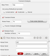
I am running transient noise and I specified 10 runs. From the output log file, I see that the 1st run takes a seed of 1 and the 2nd run takes a seed of 2. What surprises me is that these 10 runs dont in parallel. I dont think that is required.
Is there a setting or workaround to let them run in parallel?
The circuit is oscillator, so I am dealing with voltage noise not jitter.
I want to get the time domain representation of the noise but the transient noise analysis takes ways too long to simulate. Meanwhile, I get pnoise result very fast even though fmin is very low.
I want to ask how to convert pnoise to time domain process without running actual transient noise analysis. Whether doing ifft on the pnoise spectrum gives the time domain process I am looking for.
I have implemented a Common Source amplifier with current load. After simulating gain, now I want to go for Monte-Carlo Simulations for knowing statistical parameters. I have few questions?
1. What is the exact criteria for selecting number of runs of MCS? For some circuits MCS runs are selected as 100. Why the number of runs of MCS are selected as 100?
2. Is 100 times of MCS enough for predicting the possible performance of the circuit if it is manufactured later?
3. How to make sure number of runs (100 runs of MCS) are necessary for precise prediction?
4. If I simulate some bigger circuit say OTA etc. Shall I need to increase number of MCS runs?
5. Is there any literature (Book) available to support selection of no. of MCS runs for particular circuit?